Booster and brakes Repair the booster Weber and Fuel
Weber jets Cooling system Engine overhaul
Engine removal Bonnet emergency wire  Problems?
Nuts and bolts Cam shafts Rust repair on sills 1 + 2
Step by step to maintain the booster 

Here are two very informative sites about the process. Link 


Click to read more about restoring a Lockheed brake servo booster.


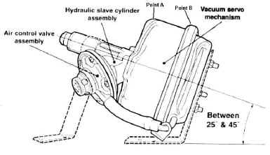
The casting 3232-656C is correct for the (English AP) Lockheed servo fitted as original equipment to the 1750 Berlina GT Veloce & Spider Veloce, listed as January 1968 onwards.


Repair kits for this type are still on the market. Pls see www.powertrackbrakes.co.uk who are very supportive. The rubber membram should say 3818-411 and the main piston is 5/6 or 15.875mm. It is a good idea to get a new air valve too and replace it at the same time.


 Please scroll down to see the step-by-step procedure.


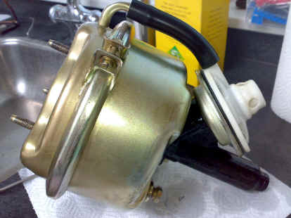
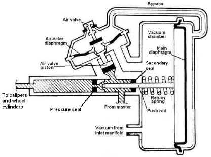
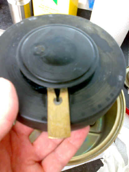
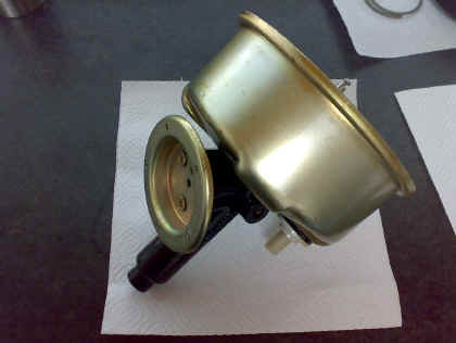
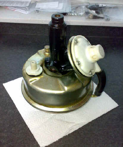
Lockheed brake servo before dismantling
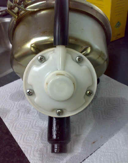

Air valve


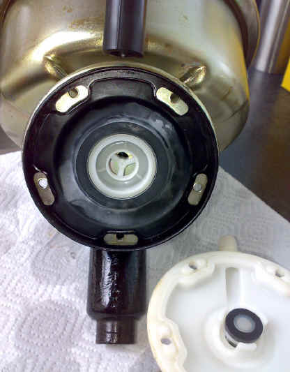
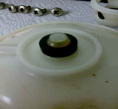
Air valve cover removed (5 screws)
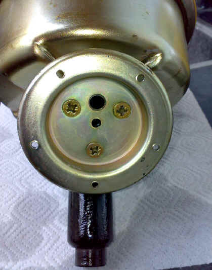

Membrane removed


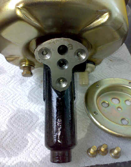
Reaction piston retaining plate removed (3 screws).u


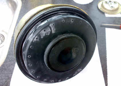
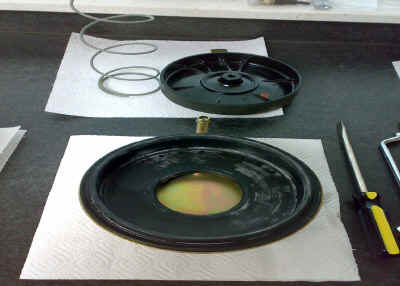
Removal of back cover, rubber bellow visible


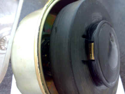
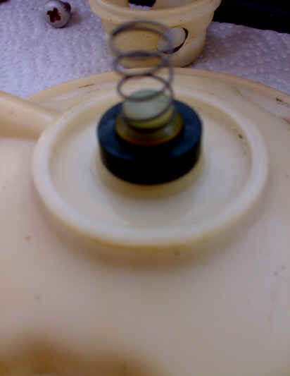
Rubber bellow gently removed, securing clamp visible


When pressing down the return spring the clamp can be taken out (should almost fall out)


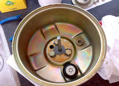
Inside of the vacuum part, one way air valve visible


After removal of the housing (3 bolts), the backup guidchable


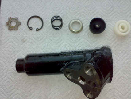
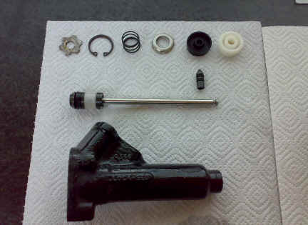
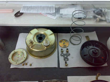
The parts in order of removal
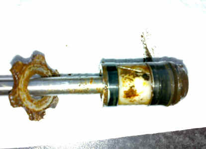
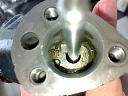
This is what storage does to brake parts i 


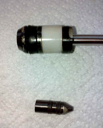
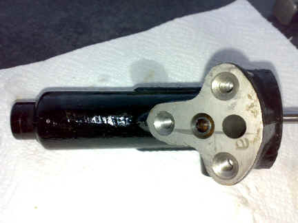
Slave cylinder and reaction piston
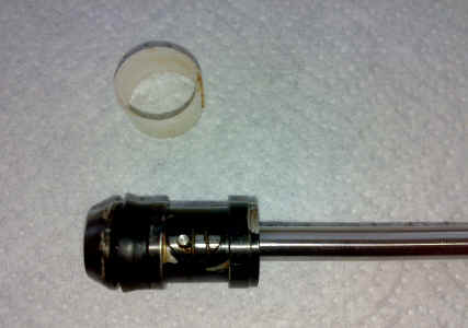
Shell removed to thoroughly clean the piston


I started rebuilding the servo because the brakes hanged on for a few more secondse direct valve operation.
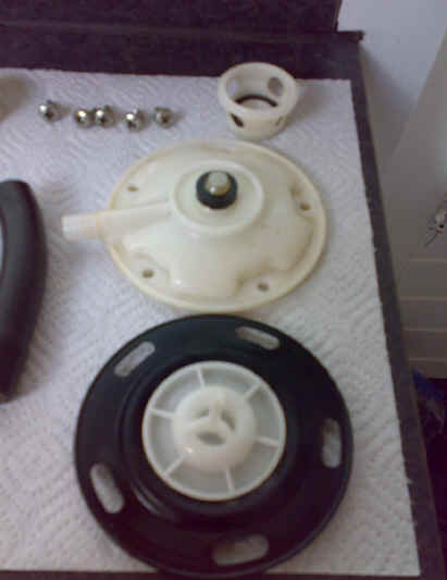
The dismantled air valve


The spring in place


All internal parts ready for reassembly


The reaction piston back in place


All components to be fitted again


Work in progress


Big return spring, plunger, bellow and back cover


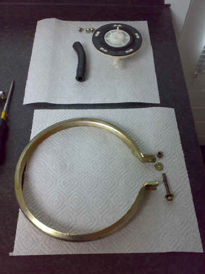
Air valve and retaining ring
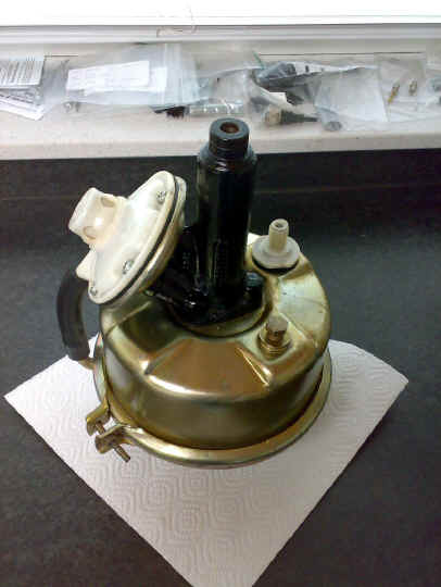
Reassembled


Reassembled hoping it will work...


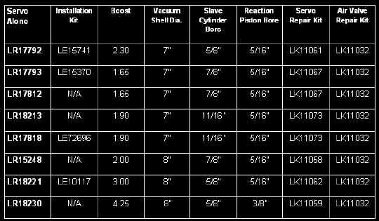
The list of Remote Brake Servo's from Lockheed with their sizes and revision kitsThanks


Remote Brake Servo

  Rebuild

Operation:

The main component parts

Engine running, brakes not applied. Vacuum from the inlet manifold is applied to the front of the main diaphragm, but also though the passage in the air-valve diaphragm, gap between the diaphragm and the air valve, the bypass pipe, to the back of the diaphragm. Thus the diaphragm has the same air pressure both sides and the return spring keeps it pressed to the back of the vacuum chamber:

Brakes applied lightly. Light fluid pressure from the master is applied to the bottom of the air-valve diaphragm, and also through the space between the push-rod and the slave cylinder and onward to the brakes. Light pressure on the air-valve piston (called the reaction valve in AP/Lockheed documents) pushes the air-valve diaphragm up to the air valve, closing off the gap between the two, but not yet lifting the air-valve off its seat. Thus there is still the same air pressure both sides of the diaphragm and it remains pressed to the back of the vacuum chamber. This lack of assistance on light pedal pressure prevents the brakes coming on harder and more suddenly than one might wish:

Heavier pressure on brake pedal. Heavier fluid pressure pushes the air-valve piston and its diaphragm further, which lifts the air-valve off its seat. This opens the air-valve allowing air at atmospheric pressure through the bypass pipe to the back of the diaphragm. With a depression on the other side the diaphragm is pulled forward, together with the push-rod, which closes off the gap between it and the slave piston, and pushes the slave piston along the bore to give a higher pressure at the outlet to the brakes than there is on the inlet from the master cylinder, which gives the 'boost' effect:

When the brake pedal is released, pressure on the air-valve piston is removed, it drops back, allowing its diaphragm and air valve to drop back also, and the latter closes the opening to the atmosphere. When the air-valve diaphragm moves away from the air valve the gap between them is opened up also, and manifold vacuum can now be applied via the bypass pipe to the back of the diaphragm again. This moves back to the rear of the chamber, pulling the push-rod back. The push-rod is connected to the slave piston with a loose connection (not shown in the diagram) so as well as opening up the gap between the two and releasing pressure from the brakes, it also pulls the slave piston back: